This resource provides comprehensive solutions to SAT Physics electromagnetism questions. Each solution includes detailed explanations, relevant formulas in LaTeX notation, and key concepts. Use these problems to strengthen your understanding of electromagnetic principles for the SAT Physics Subject Test.
The primary of a transformer is connected to a voltage source with two components: an alternating current (AC) component of 120 V and a steady direct current (DC) component of 5 V. The primary has 300 turns and the secondary has 6000 turns. What is the voltage at the output of the secondary?
Transformers only work with alternating current (AC). A changing magnetic field in the primary coil induces a voltage in the secondary coil. Steady DC current produces a constant magnetic field that doesn't change with time, so it cannot induce a voltage in the secondary coil.
The transformer equation relates the voltages and number of turns:
\[ \frac{V_s}{V_p} = \frac{N_s}{N_p} \]Where:
Substituting the values:
\[ \frac{V_s}{120\ \text{V}} = \frac{6000}{300} = 20 \] \[ V_s = 120 \times 20 = 2400\ \text{V} \]The DC component (5 V) is blocked by the transformer, so only the AC component is transformed.
Answer: B) 2400 V AC onlyAn electric motor transforms:
An electric motor converts electrical energy into mechanical energy through the interaction of magnetic fields and current-carrying conductors. This is based on the motor effect, where a current-carrying conductor in a magnetic field experiences a force.
The reverse process (mechanical to electrical) is performed by electric generators.
Answer: B) electrical energy into mechanical energyA transformer with 80% efficiency is connected to a 50 V AC source. The secondary voltage and current are 500 V and 0.1 A respectively. What is the current in the primary?
Transformer efficiency (\(\eta\)) is defined as:
\[ \eta = \frac{\text{Output Power}}{\text{Input Power}} = \frac{P_{\text{out}}}{P_{\text{in}}} \]For a transformer:
\[ \eta = \frac{V_s I_s}{V_p I_p} \]Where:
Rearranging the formula to solve for \(I_p\):
\[ I_p = \frac{V_s I_s}{\eta V_p} = \frac{(500\ \text{V})(0.1\ \text{A})}{(0.8)(50\ \text{V})} \] \[ I_p = \frac{50\ \text{W}}{40\ \text{W/A}} = 1.25\ \text{A} \]Note: For an ideal (100% efficient) transformer, \(V_p I_p = V_s I_s\). Real transformers have losses due to resistance, hysteresis, and eddy currents.
Answer: C) 1.25 AA bar of length \(L\) slides along electrical wires perpendicular to a magnetic field \(B\) directed out of the page. The bar and wires (including resistor \(R\)) form a closed circuit. Which action(s) will increase the current through \(R\)? (Assume negligible resistance in wires and bar.)

The motional electromotive force (EMF) generated in the moving bar is given by:
\[ \mathcal{E} = B L v \]Where:
The current in the circuit is given by Ohm's Law:
\[ I = \frac{\mathcal{E}}{R} = \frac{B L v}{R} \]From this equation, we can see that:
Therefore, actions II and III would increase the current.
Answer: D) II and/or IIIA permanent magnet is inserted at constant speed into a loop from the left and exits from the right as shown. While the magnet moves from left to right:
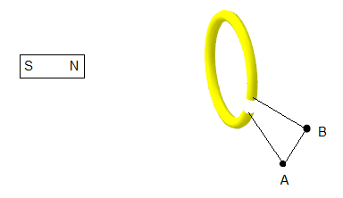
The direction of induced current is such that it opposes the change in magnetic flux that produced it. This is a consequence of the conservation of energy.
As the north pole of the magnet approaches the loop (from the left), the magnetic flux through the loop increases. According to Lenz's Law, the induced current will create a magnetic field that opposes this increase. Using the right-hand rule, this requires a current flowing from A to B.
When the magnet is exiting (south pole leaving the loop on the right side), the magnetic flux through the loop decreases. The induced current will now create a magnetic field that opposes this decrease, which requires the current to reverse direction (from B to A).
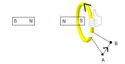
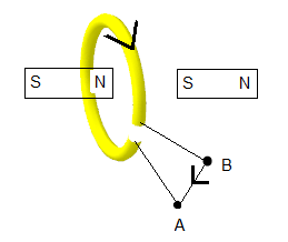
Thus, the current changes direction during the process: A→B when the magnet enters, and B→A when it exits.
Answer: B) the current in the loop will be from A to B and then from B to AA stationary magnet is pushed closer to a loop and then stopped. Which graph best represents the induced current in the loop?
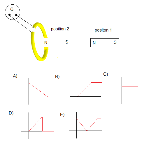
According to Faraday's Law of electromagnetic induction:
\[ \mathcal{E} = -\frac{d\Phi_B}{dt} \]Where \(\Phi_B\) is the magnetic flux. The induced current is proportional to the rate of change of magnetic flux.
Analyzing each phase:
The correct graph must show zero current initially, then non-zero current while the magnet is moving, then zero again when it stops.
Answer: D (Graph showing current only while the magnet is moving)A uniform magnetic field \(B\) is parallel to a rectangular surface with area 0.05 m² and field strength 0.5 T. What is the magnetic flux through the rectangle?
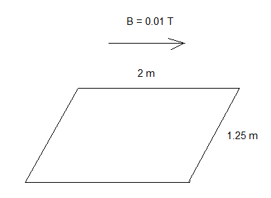
Magnetic flux (\(\Phi_B\)) through a surface is given by:
\[ \Phi_B = B A \cos\theta \]Where:
Since the magnetic field is parallel to the surface, it is perpendicular to the surface normal. Therefore, \(\theta = 90^\circ\) and \(\cos 90^\circ = 0\).
\[ \Phi_B = (0.5\ \text{T})(0.05\ \text{m}^2)(\cos 90^\circ) = (0.5)(0.05)(0) = 0\ \text{Wb} \]Note: Magnetic flux is maximum when the field is perpendicular to the surface (\(\theta = 0^\circ\)) and zero when parallel to the surface (\(\theta = 90^\circ\)).
Answer: B) 0 WbFor a transformer that is not 100% efficient, which statement must be true?
The efficiency (\(\eta\)) of a transformer is defined as:
\[ \eta = \frac{\text{Output Power}}{\text{Input Power}} = \frac{V_s I_s}{V_p I_p} \]For a transformer that is not 100% efficient, \(\eta < 1\). Therefore:
\[ \frac{V_s I_s}{V_p I_p} < 1 \] \[ V_s I_s < V_p I_p \]The input power exceeds the output power due to energy losses (resistive heating, hysteresis, eddy currents).
Answer: E) \(V_s I_s < V_p I_p\)Which law determines the direction of induced current in a loop near a moving magnet?
While Faraday's Law tells us that an EMF will be induced when magnetic flux changes, Lenz's Law specifically determines the direction of the induced current.
Answer: D) Lenz's lawWhich statements are true about Lenz's Law?
Evaluating each statement:
I. It obeys Newton's Third Law: True. The force on the magnet due to the induced current is equal and opposite to the force causing the change in flux.
II. It obeys the conservation of energy: True. Lenz's Law ensures that the induced current opposes the change, meaning work must be done to cause the change. This work becomes the electrical energy in the induced current, conserving energy overall.
III. It may be used to find the direction of induced current: True. This is the primary application of Lenz's Law.
Answer: A) I, II, and IIISAT Physics Electromagnetism Practice Questions & Solutions
For more physics resources, visit ProblemsPhysics.com